CIMC Module And Wiring

CIMC Module And Wiring
Parameters/Description

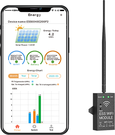
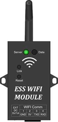
WIFI module picture and instruction
Server LED:Network status indicator
1S Flash:Network abnormal,Server connection failure
0.3S Flash:Distribution network state
Light on:Network normal,Server connection success
Data LED:Data is transmission, flash once every 10 minutes
Link button:Distribution network button,Press and hold to enter the distribution network state
Reset button:module restart button

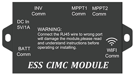
CIMC module and wiring instruction
MPPT1&2 Comm:RJ45 blue 1.5M 8P network cable is adopted to connect with MPPT solar charger Remote Comm
INV Comm:RJ45 blue 1M 8P network cable is adopted to connect with inverter LCD Remote Port
BATT Comm:RJ11 blue 4M 8P network cable is adopted to connect with battery pack RJ45 Comm
WIFI Comm:RJ45 blue 10M 8P network cable is adopted with WIFI module RJ45 Comm
DC In5V/1A:Backup 5VDC power interface

Accessories
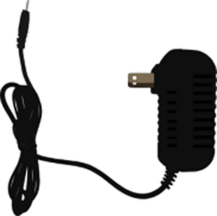
WIFI module 5V external supply When the module is placed in a strong WiFi signal position with 10m cable, the WiFi module itself needs to be equipped with 5V external power supply to ensure stable signal transmission